
My friend was trying to make a device that he could put on his bike and use the energy from the wheels spinning to charge his phone. He had an alternator already lying around that he planned to use, so he had to convert the AC voltage to DC and also regulate it to a proper 5V output so he could charge the battery.
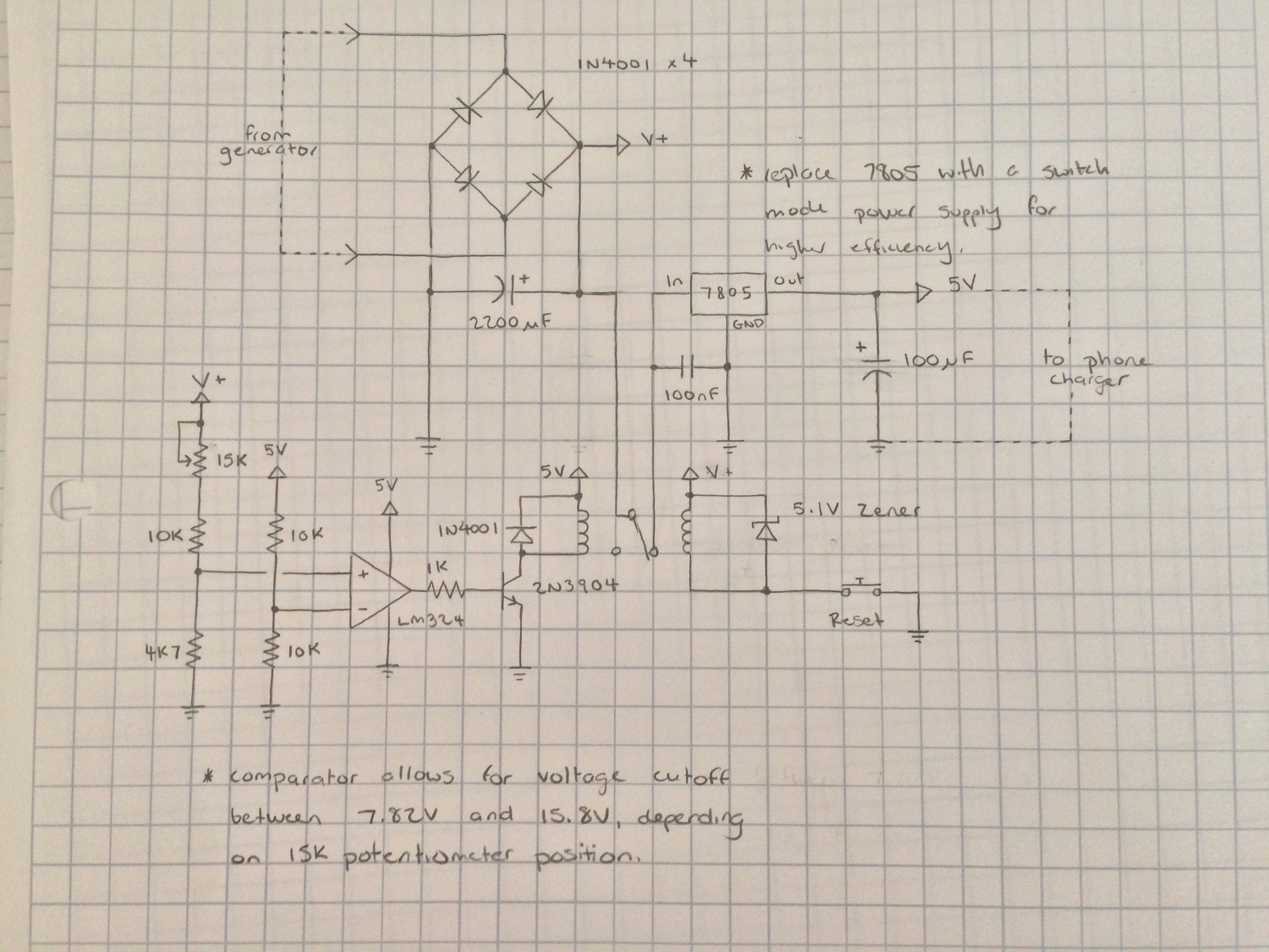
I was able to design a circuit from scratch, that took the AC input from his alternator and gave him a 5VDC output. Since designing that section was a bit too easy (only a full bridge recitifier and a 7805), I incorporated an over-voltage protection circuit so that if the bike goes really fast and the voltage on the input goes beyond a certain threshold, it would shut itself off and prevent damage to the regulator.
Here is the circuit I designed on paper first:
I then moved my design from paper on to Altium Designer, used pre-built schematic symbols from the Miscellaneous Devices and Miscellaneous Connectors libraries, and created this:

After that I designed all the custom footprints inside my own PCB library, and after laying out everything onto a PCB, I routed, changed the board size, and used copper pour to finish it off. Here is the final product:

One thing I still need to get more familiar with is using the Design Rules in Altium. Right now I have a basic understanding for changing trace width and component clearance, but I know there’s a lot more I can take advantage of if I learn how to set it up right.
