STM32 Bare Bones Circuit

Today I received my order of parts from Digikey. I ordered the bare STM32L053 microcontroller and a programmer for it, so that I could practice soldering it and code it from scratch. I soldered the bare chip onto a breakout board I had lying around. The pin pitch is 0.5mm on a 7×7 LQFP48 chip. In WorldSkills I’ll only be required to solder a minimum of 0.65mm pitch, and since I was fine with soldering this one, I should be ok for WorldSkills too. I hand soldered this chip, but I ordered two so I’ll try the hot air soldering and see if it goes any better or worse.

I created a simple program using the HAL libraries to blink an LED connected to pin PB12. After connecting everything up I was surprised that it actually worked first try without any modifications!

I’m going to be doing most of my programming from now on using this bare-bones circuit, because I don’t like all the extra peripherals they added on the development board that I was using.

Here’s a picture of the finished circuit:

IMG_0350

Car Radio Project – Part 3 (Raspberry Pi)

After messing around with my FM circuit, I was looking on the internet to see how FM radio stations broadcast in stereo. While doing so, I found a cool little project using the Raspberry Pi, which turns it into an FM radio!

http://makezine.com/projects/raspberry-pirate-radio/

I did some research, and eventually came across these site, which allows the code to be run on a Raspberry Pi 3, which is what I wanted since it has Bluetooth.

https://github.com/cerberus98/PiFmRds
https://raspberrypi.stackexchange.com/questions/47708/setup-raspberry-pi-3-as-bluetooth-speaker

Building off that code, I was able to set the Raspberry Pi up as a Bluetooth audio receiver which connects to your phone and is able to transmit the audio signal over FM. Basically it’s like a Bluetooth speaker, but instead of the speaker, it becomes an FM transmitter.

I won’t go into the details of how I set it up here, but I will post the short script that I wrote which automatically connects to my or my friend’s iPhone, and starts broadcasting to FM. This eliminates the need for a mouse and keyboard which makes the setup ideal for the car!

(code posting soon)


Car Radio Project – Part 2 (FM Radio Circuit)

Building off my previous blog post, I tried building an FM circuit instead of AM. I took the circuit from this book: More Electronic Gadgets For The Evil Genius by Bob Iannini.

IMG_0323

img_0320.jpg

I took this from the project “Wireless FM Repeater”

After creating the circuit on a breadboard, I did some testing but found that the circuit didn’t function very well. I fiddled around with it for quite a while, and eventually modified the circuit to this below, which I modelled in Altium.

FM sch

I also created a board layout for this circuit, and created the required component footprints from scratch. Unfortunately, I decided not to get this board milled because of reasons revealed in Part 3. 🙂

FM pcb

It took me about half an hour to complete the Altium design from start to finish.

Since I didn’t have time to mill the board, I decided to build the circuit on a small piece of stripboard:

IMG_0324

The result is pretty good. The circuit is VERY prone to interference, but if you stand back, the frequency is stable and transmits a good audio signal with respectable sound quality. The only downside is the signal is down-mixed to mono instead of a good stereo signal. The 2 pin header is for power (12V in) and the AUX input jack is on the left. By experimentation, I found that the signal in to the device needs to be pretty loud in order for it to transmit a good audio signal. Building an amplifier between the phone and this circuit would probably fix it.

Car Radio Project – Part 1 (AM Radio Experimentation)

My friend recently got a new car and we were hoping to find an AUX input somewhere on it so we could use our phones to play music. Unfortunately we couldn’t find one, so we could only use the CD drive, or the FM/AM radio.

Instead of buying a new stereo system for his car, I suggested I make a radio transmitter so that we could plug our phones into that, and tune the car’s radio into the set frequency and listen that way.

I started experimenting with amplitude modulation, since I thought it would be simpler and since it’s lower frequency, less care has to be taken about interference. I created this circuit based off a video from Afrotechmods:

I created it on a breadboard:

IMG_0319

I removed the antenna from the circuit in this photo

And it worked pretty well! The frequency was stable at 1040kHz (adjustable slightly witht the blue pot), but the only problem was that the sound quality was relatively poor when compared to the original (since it’s AM), and it didn’t have much range, even with the antenna attached. In the next post, I’ll be experimenting with frequency modulation and seeing if it has any benefits.

RLC Theory

I started browsing through past WorldSkills projects, and realized that they had a lot of filter circuits in the Test Projects. Since I had no idea of anything about filters, I decided to start learning about them so I’d be prepared.

Today I started with simple RLC theory. Learning about the reactance of a capacitor and inductor, and how to calculate the voltage out of a RC or RL high or lowpass filter, given the component values and the frequency and amplitude of the AC input.

To test my knowledge I made a simple RC filter on a breadboard, as well as in a simulator. I measured the voltage out on the breadboard as well as in the simulator and compared that to my math on paper. Thankfully my math checked out.

Here’s a picture of the circuit on the breadboard, the scope readings, the simulated circuit and the math I did on paper:

IMG_0262

NewFile0

Capture

IMG_0257

I found this video super helpful: https://www.youtube.com/watch?v=FEERuJlwBxE
It helped me understand how the capacitor and inductor introduce a phase difference into the signal, and therefore can’t be calculated just like a normal resistor in a voltage divider.

LC Meter

After doing some work with LC tank circuits, I found that I often needed to measure the value of certain inductors / capacitors. Unfortunately, I don’t have a tool that measures inductance and the Fluke meter can only measure capacitors in the nanofarad range. I decided to go online and look for an LC meter circuit so I could re-engineer it in Altium and practice more with making PCB’s.

I found a circuit from this site:
https://sites.google.com/site/vk3bhr/home/index2-html

I was able to redraw the schematic:

Schematic 2

As well as create special PCB footprints for all the components, since I plan on actually making this LC meter in the future:

7805

Footprint for the voltage regulator (surface mount). I didn’t bother to add any silkscreen because the laser engraver at my school doesn’t print it.

Here is the finished layout of the PCB:

layout 2

Girls Do Code Soldering Practice

Mt shop teacher participated in an event last Saturday called Girls Do Code. He was leading the electronics division, and he set up a mini-soldering project for the girls to complete. It was a simple 4017 counter using a 555 oscillator. Since most of the girls had never soldered before, there wouldn’t have been enough time for the girls to solder the whole board, so my teacher asked me if I wanted extra practice by soldering. I thought it would be a great opportunity, especially because the boards were etched in my school and they didnt have any solder mask. In EuroSkills one of my poorest areas was in the soldering task, because I designed the component pads too small and wasn’t familiar with my tools. I didn’t design these boards, but they had larger pads which made soldering it so much easier. I’m no longer worried about my soldering skills for the milled boards, because I realized the problem at EuroSkills was when I designed it in Altium.

Here’s all the finished boards, and a close up of the backside of one of them:

IMG_0035

The board still looks a little messy; it hadn’t been cleaned off yet.

IMG_0039

20 boards total

Phone Charger Circuit

My friend was trying to make a device that he could put on his bike and use the energy from the wheels spinning to charge his phone. He had an alternator already lying around that he planned to use, so he had to convert the AC voltage to DC and also regulate it to a proper 5V output so he could charge the battery.

I was able to design a circuit from scratch, that took the AC input from his alternator and gave him a 5VDC output. Since designing that section was a bit too easy (only a full bridge recitifier and a 7805), I incorporated an over-voltage protection circuit so that if the bike goes really fast and the voltage on the input goes beyond a certain threshold, it would shut itself off and prevent damage to the regulator.

Here is the circuit I designed on paper first:

img_0037.jpg

I then moved my design from paper on to Altium Designer, used pre-built schematic symbols from the Miscellaneous Devices and Miscellaneous Connectors libraries, and created this:

phone charger sch


After that I designed all the custom footprints inside my own PCB library, and after laying out everything onto a PCB, I routed, changed the board size, and used copper pour to finish it off. Here is the final product:

phone charger

One thing I still need to get more familiar with is using the Design Rules in Altium. Right now I have a basic understanding for changing trace width and component clearance, but I know there’s a lot more I can take advantage of if I learn how to set it up right.

Digital Clock

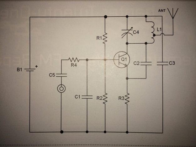
Today I challenged myself with a circuit design task. Using the parts I had at my workbench, I wanted to make a device that could accurately keep time. I also recently discovered people were making “binary clocks” and thought it would be cool to build it. Originally, my plan was to use a 32.768kHz crystal and use lots of JK flip flops to divide it’s frequency by 2 and eventually get a frequency of 1Hz, but I realized quickly that I’d need way too many (15 to be exact) and I only had 4 to use for the entire project. I decided to use a 4 pin crystal oscillator instead, but I was also able to use a 4MHz, 2 pin crystal wired to a transistor to produce an oscillation.

I chose a 1MHz oscillator because I had it around from previous AM radio experiments. However, 1MHz can’t be divided by 2 to get 1Hz. I realized it had to be divided by powers of 10. Thankfully, I discovered I had binary counters lying around that just happened to count to 10. I used 6 of them in series to divide my frequency by a total factor of 10^6, or 1000000, so my final output frequency was 1Hz.

For the seconds counter, I decided to cheat a little to save on my flip flop usage, and used an LED bar graph I had lying around with a 4017 decade counter. This was pretty simple to wire up because I’ve used it in the past; I connected the 1Hz signal to the clock in pin, and the carry out pin connects to the next stage of the circuit (0.1Hz).

The next stage of the circuit is where I implemented the JK flip flops (3 of them). Since the tens digit in seconds needs to only count to 5, I was able to get away with 3 LED’s (which shows binary from 0-7). I wired J and K to +5V, and the clock in pin to the 0.1Hz signal from the 4017.

Something I learned while building this circuit is that the succesive JK flip flop needs to be connected to !Q, instead of Q of the previous flip flop, for the binary sequence to count correctly. To show why, here is part of the binary sequence for 3 bits:

Bit 2       Bit 1       Bit 0
0              0              0
0              0              1
0              1              0
0              1              1
1              0              0

Notice how bit 1 only toggles when bit 0 changes states from 1-0. This can be called that bit’s falling edge. Since the 4027 JK flip flop toggles Q on the rising edge of the clock signal input, then the wire connecting it to the previous flip flop must be inverted. Instead of using a dedicated IC, why not just use the !Q pin, which is already on the 4027 IC to save parts.

Since the circuit right now will count the tens digit up to 7 then reset to 0, I needed to make another module that would reset all the flip flops when the count goes past 5. I thought this would be easy, since 6 in binary is 1 1 0, and I could just put an AND gate connecting to bit 2 and bit 1, connect it’s output to the clear pin on each flip flop, and everything would work. However, when transitioning from 0 1 1 to 1 0 0, all 3 outputs are on for a brief period of time, which causes the AND gate to false trigger and the second counter never gets past 39. I realized that I had to make another circuit that would reject false triggers from the AND gate, and allow the real ones to pass through.

I was able to come up with this:

mini-diagram


I configured the 555 to operate in monostable mode, meaning it won’t oscillate, but when the trigger pin goes high, it will output a single pulse for a set period of time (determined by the RC constant), then go low and stay low. I thought I could fine tune the length of this pulse to be just a tiny bit longer than the false trigger coming from the AND gate, but short enough so that it doesn’t create a noticeable delay for humans to see. Using a comparator, I connected the 555’s output pulse into the inverting input of the comparator and the output of the AND gate to the non-inverting input through a voltage divider.

When the AND gate false triggers, it will send a signal to the trigger pin of the 555, causing it to go high, as well as a signal to the non-inverting input of the comparator. Since the non-inverting input’s voltage will be less than the inverting input (because of the voltage divider), the comparator will remain off. During a false trigger, the AND gate’s output will turn off long before the 555 pulse goes low, so the inverting input of the comparator will remain high while the non-inverting input will go back low again. This keeps the comparator in the off state.

However, when the AND gate false triggers, the 555’s pulse will turn off before the AND gate’s output does (since the AND gate will remain on for 20 seconds unless it’s reset!). This causes the inverting input of the comparator to go low, but the non-inverting input is still high because of the AND gate, so the output of the comparator finally goes high. The output is connected to the clear pins of Bit 2 and Bit 1 (Bit 0 doesn’t need it because it goes to 0 automatically for 6 as well), so the counter resets itself to 0 and counts up to 5 again.

Overall, this creates a circuit that can count from 0-59 seconds. Obviously this circuit could be duplicated so that it could be a little more useful and count up to an hour of time. I just didn’t want to make it because it’s a lot of wiring for a breadboard!

Here is the overall schematic (I have boxed in each section to make each part easier to understand):

overall.PNG

Here is what I made on the breadboard:

img_20170204_0812026611

The full working circuit using the 1MHz crystal as a clock input.

img_20170204_0811548522

Proof that I can use a regular 2 pin crystal for a wider range of frequencies.

Programming the STM32

I was recently given some more information about the programming task at WorldSkills. I had already received a STM32L0 Discovery Board in the mail, but I didn’t know which methods of programming would be allowed at WorldSkills. My Expert sent me a document which explained how to get started and initialize an LED blinking, so I followed the instructions, and success! However, I didn’t want to write a blog post about just blinking an LED, so I decided to progress a little further with enabling different peripherals on the device.

I started with the USART. This is always a great thing to start out with in my opinion, because once that’s working, it’s easy to troubleshoot other aspects of the code because register values can simply be sent over the UART. STM32Cube is what will be used in WorldSkills to initialize all the peripherals and GPIO on startup. It’s a graphical program that uses the HAL libraries provided by STMicroelectronics. I think the program is very easy to use and I had this entire project up and running in a fraction of the time that it would have took on another platform without this tool. However, I feel uneasy using it because I’m used to writing all the code myself and this tool generates everything for me. I don’t have any control over the individual registers which is how I normally program, and the code is a lot longer than anything I would write (because it’s bloated with uneccesary code for other specific applications), which makes me more stressed out about bugs in the future.

In any case, I was able to complete a “loopback program”, which uses the RX and TX pins and sends back everything that was sent to it. I used a circular buffer with DMA (this is actually my first time using DMA in any microcontroller), because all the other library functions didn’t work the way I wanted. I have an rxbuffer of 32 bytes in size, that holds all incoming data (it can be made larger or smaller depending on the application). If more than 32 bytes is received, rxbuffer starts filling from address 0 and overwrites anything in there previously. There is a program in the main while loop that simply prints out the buffer and waits for a second just so the serial port doesn’t get overloaded. I have the microcontroller connected via an FTDI cable to my PC, running a serial terminal where I can send and receive data.

DMA makes programming easy. It essentially writes the incoming characters directly into a specified address in memory so the CPU doesn’t have to trigger an interrupt whenever there is a new character received. The circular array makes things easy so that the CPU doesn’t have to constantly read and reset the array, it can read from it when it wants to.

Here is the main code that I created (just main!!):

uint8_t rxbuffer[32];

int main(void) {
    HAL_Init();
    SystemClock_Config();
    MX_GPIO_Init();
    MX_DMA_Init();
    MX_USART1_UART_Init();
    HAL_UART_Receive_DMA(&huart1, rxbuffer, 32);
    while(1) {
        HAL_UART_Transmit(&huart1, rxbuffer, 32, 1000);
        // keep timeout at 1000 to prevent cutoff of large data
        HAL_UART_Transmit(&huart1, "\n", 1, 1000);
        HAL_Delay(1000);
    }
}